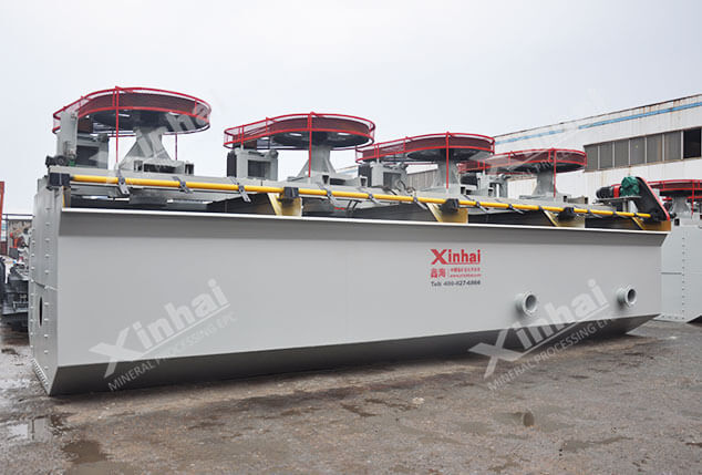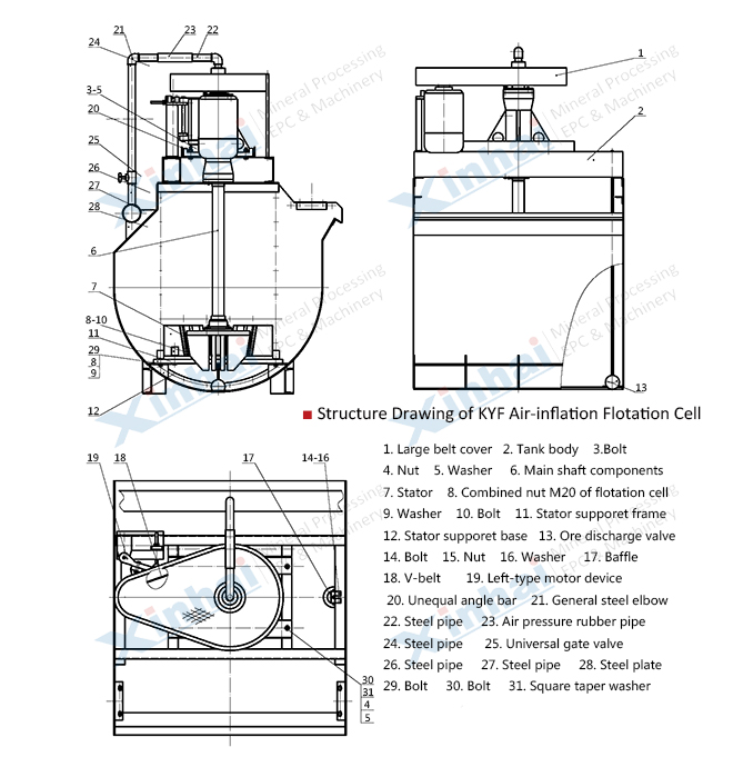
[Introduction]: An air-inflation mechanical agitation flotation cell without slurry suction (This type of cell is designed referring to Finland Autoquenpu OK flotation cell).
[Capacity]: 0.2~38m³/min
[Improvement]: Cone impeller is equipped with the vanes sloping backward at a certain angle, which makes strong agitation ability and simple structure. The impeller chamber is equipped with multi holes cyinder air distributor. Adpot the U-shaped tank with little sand sediment.
The impeller of KYF flotation cell is conical impeller with backward angle of blade, which has simple structure and strong stirring capacity.
There are multi-empty cylindrical air distributor in impeller cavity, which disperses air evenly and makes a good combination of air and slurry.
Small diameter of impeller with slow peripheral speed and low energy consumption, which save energy 30-50%.
Good ore suspension and high flotation indexes.
U-shape cell body is applied to reduce the tailing deposit.
Light wear of quick-wear part with a long working life.
Mechanical agitation, without self-air-inflation and self-priming pulp. The ladder configuration between work room is essential.
It can be combined with XCF flotation cell in combined flotation unit as straight tank.

KYF air inflation floatation cell working principle: when theflotation cellis at work, the rotation of impeller makes the slurry all around via tank bottom absorbed from downside of impelle into inner-vanes of impeller, where low pressure air produced by the blower goes into via hollow shaft and the air distributor of impeller chamber at the same time. After fully mixture of the slurry and air among vanes, they are pushed out in inclined upward direction from upper half of the impeller around, and go into the tank via steady f\ow and orientation by the stator. Air bubbles rise to the foam stability area, and after concentration process, the froths overflow from the overflow weir into the froth tank. Another part of the slurry flows to ward the lower part of impeller, then through the impeller agitation, they are mixed together to form mineral laden bubbles again, and the rest of the slurry will flow to the next tank to become tailings eventually.
| Model | Effective Volume (m3) | Capacity (m3/min) | Impeller Diameter (mm) | Impeller Revolution (r/min) | Air Pressure of Blower (kPa) | Max. Air Inflation Volume (m3/m2.min) | Motor Power for Agitation (kW) | Motor Power for Scraper (kW) | Weight (kg) |
| KYF-1 | 1 | 0.2~1 | 340 | 281 | ≥ 12.6 | 2 | 4 | 0.75 | 903 |
| KYF-2 | 2 | 0.4~2 | 410 | 247 | ≥ 14.7 | 2 | 5.5 | 1.1 | 1419 |
| KYF-3 | 3 | 0.6~3 | 480 | 219 | ≥ 19.8 | 2 | 7.5 | 1.5 | 1885 |
| KYF-4 | 4 | 1.2~4 | 550 | 200 | ≥ 19.8 | 2 | 11 | 1.5 | 2206 |
| KYF-8 | 8 | 3.0~8 | 630 | 175 | ≥ 21.6 | 2 | 15 | 1.5 | 3984 |
| KYF-10 | 10 | 4.0~10 | 630 | 192 | ≥ 21.6 | 2 | 22 | 1.5 | 4406 |
| KYF-16 | 16 | 4.0~16 | 740 | 160 | ≥ 25.5 | 2 | 30 | 1.5 | 5900 |
| KYF-24 | 24 | 4.0~24 | 800 | 150 | ≥ 30.4 | 2 | 30 | 1.5 | 7500 |
| KYF-38 | 38 | 10.0~38 | 880 | 139 | ≥ 34.3 | 2 | 45 | 1.5 | 10300 |